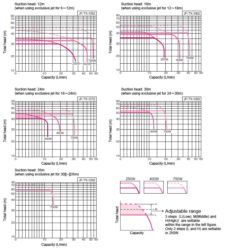
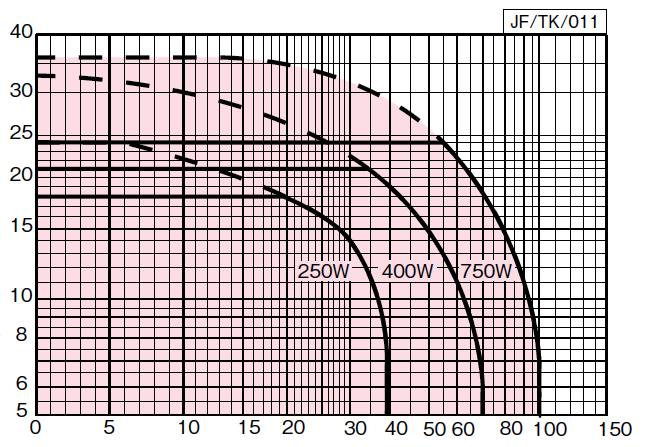
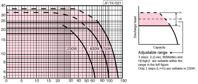
Selection chartNOTEActual performance may slightly differ from the values in table and chart. Values in table show standard characteristics.
(in case using φ100 jet) For deep well 250~750W
Inquire about characteristics of [[φ]]75 and [[φ]]50 jet
Specificiation tableNOTEActual performance may slightly differ from the values in table and chart. Values in table show standard characteristics.
60Hz
For deep well, small water amount stop rate: 4L/min, accumulator volume: 1L
| 25 | JF250S | 250 | Single phase 100V | 12 | 26 | 24/24/19 | 14
[20] | 18
[24] | 30 | 30 | 100 (4B) or more | N20 or N30 (6~12m) | 75 (3B) or more | R01(6~12m) | 50 (2B) exclusive | S01
(6~18m) | DL |
| 25 | JF250S | 250 | Single phase 100V | 18 | 32 | 16/10/14 | 14
[20] | 18
[24] | 30 | 30 | 100 (4B) or more | N21 or N31 (12~18m) | 75 (3B) or more | R02(12~18m) | 50 (2B) exclusive | S01
(6~18m) | DL |
| 25 | JF250S | 250 | Single phase 100V | 24 | 38 | 10.5/-/- | 14
[20] | 18
[24] | 30 | 30 | 100 (4B) or more | N21 or N31 (18~24m) | 75 (3B) or more | ― | 50 (2B) exclusive | ― | DL |
| 25 | JF400S
JF400S2
JF400T | 400 | Single phase 100V (Single phase 200V), or Three phase 200V | 12 | 29 | 38/30/- | 17
〈23〉
[29] | 21
〈27〉
[33] | 30 | 30 | 100 (4B) or more | N20 or N30 (6~12m) | 75 (3B) or more | R01(6~12m) | 50 (2B) exclusive | ― | DL |
| 25 | JF400S
JF400S2
JF400T | 400 | Single phase 100V (Single phase 200V), or Three phase 200V | 18 | 35 | 28/17/22 | 17
〈23〉
[29] | 21
〈27〉
[33] | 30 | 30 | 100 (4B) or more | N22 or N32 (12~18m) | 75 (3B) or more | R02(12~18m) | 50 (2B) exclusive | S01
(12~24m) | DL |
| 25 | JF400S
JF400S2
JF400T | 400 | Single phase 100V (Single phase 200V), or Three phase 200V | 24 | 41 | 17/-/16 | 17
〈23〉
[29] | 21
〈27〉
[33] | 30 | 30 | 100 (4B) or more | N22, N23 or N32, N33 (18~24m) | 75 (3B) or more | ― | 50 (2B) exclusive | S01
(12~24m) | DL |
| 25 | JF400S
JF400S2
JF400T | 400 | Single phase 100V (Single phase 200V), or Three phase 200V | 30 | 47 | 11/-/- | 17
〈23〉
[29] | 21
〈27〉
[33] | 30 | 30 | 100 (4B) or more | N23 or N33 (24~30m) | 75 (3B) or more | ― | 50 (2B) exclusive | ― | DL |
| 25 | JF750
JF750S2 | 750 | Three phase (Single phase 200V) | 12 | 32 | 51/32/- | 20
〈26〉
[32] | 24
〈30〉
[36] | 30 | 30 | 100 (4B) or more | N20 or N30 (6~12m) | 75 (3B) or more | R01(6~12m) | 50 (2B) exclusive | ― | DL |
| 25 | JF750
JF750S2 | 750 | Three phase (Single phase 200V) | 18 | 38 | 39/23/27 | 20
〈26〉
[32] | 24
〈30〉
[36] | 30 | 30 | 100 (4B) or more | N22 or N32 (12~18m) | 75 (3B) or more | R01(12~18m) | 50 (2B) exclusive | S01
(12~24m) | DL |
| 25 | JF750
JF750S2 | 750 | Three phase (Single phase 200V) | 24 | 44 | 29/12/21 | 20
〈26〉
[32] | 24
〈30〉
[36] | 30 | 30 | 100 (4B) or more | N22 or N32 (18~24m) | 75 (3B) or more | R02(18~24m) | 50 (2B) exclusive | S01
(12~24m) | DL |
| 25 | JF750
JF750S2 | 750 | Three phase (Single phase 200V) | 30 | 50 | 19/-/- | 20
〈26〉
[32] | 24
〈30〉
[36] | 30 | 30 | 100 (4B) or more | N23 or N33 (24~30m) | 75 (3B) or more | ― | 50 (2B) exclusive | ― | DL |
| 25 | JF750
JF750S2 | 750 | Three phase (Single phase 200V) | 35 | 55 | 14.5/-/- | 20
〈26〉
[32] | 24
〈30〉
[36] | 30 | 30 | 100 (4B) or more | N23 or N33 (30~35m) | 75 (3B) or more | ― | 50 (2B) exclusive | ― | DL |
*Operation characteristics enclosed in < > shows the value when Fine sensor set at M, and [ ] shows the value when Fine sensor set at H. Default setting of 250W model is H, and 400W & 750W model are M.
*1 Capacity indicates the value as following array; φ100 Jet/ φ75 Jet/ φ50 Jet/
NOTE) 25mm Suction pipe and Pressure pipe in φ75 Jet, 25mm pressure pipe in φ50 Jet. According to the combining Jet, prepare different dia. joint (32 x 25)
*2 Jet set N20~N23 have built-in Foot valve.
Also, use Jet set N30~N33 in case the well water level drops under Jet part. (It is not capable of drainage in the pipe, because of foot valve without lever.)
For deep well, small water amount stop rate: 4L/min, accumulator volume: 1L
| 25 | JF250S | 250 | Single phase 100V | 39 | 85 | 24/24/19 | 14
[20] | 18
[24] | 30 | 30 | 100 (4B) or more | N20 or N30 (6~12m) | 75 (3B) or more | R01(6~12m) | 50 (2B) exclusive | S01
(6~18m) | DL |
|---|
| 25 | JF250S | 250 | Single phase 100V | 59 | 104 | 16/10/14 | 14
[20] | 18
[24] | 30 | 30 | 100 (4B) or more | N21 or N31 (12~18m) | 75 (3B) or more | R02(12~18m) | 50 (2B) exclusive | S01
(6~18m) | DL |
|---|
| 25 | JF250S | 250 | Single phase 100V | 78 | 124 | 10.5/-/- | 14
[20] | 18
[24] | 30 | 30 | 100 (4B) or more | N21 or N31 (18~24m) | 75 (3B) or more | ― | 50 (2B) exclusive | ― | DL |
|---|
| 25 | JF400S
JF400S2
JF400T | 400 | Single phase 100V (Single phase 200V), or Three phase 200V | 39 | 95 | 38/30/- | 17
〈23〉
[29] | 21
〈27〉
[33] | 30 | 30 | 100 (4B) or more | N20 or N30 (6~12m) | 75 (3B) or more | R01(6~12m) | 50 (2B) exclusive | ― | DL |
|---|
| 25 | JF400S
JF400S2
JF400T | 400 | Single phase 100V (Single phase 200V), or Three phase 200V | 59 | 114 | 28/17/22 | 17
〈23〉
[29] | 21
〈27〉
[33] | 30 | 30 | 100 (4B) or more | N22 or N32 (12~18m) | 75 (3B) or more | R02(12~18m) | 50 (2B) exclusive | S01
(12~24m) | DL |
|---|
| 25 | JF400S
JF400S2
JF400T | 400 | Single phase 100V (Single phase 200V), or Three phase 200V | 78 | 134 | 17/-/16 | 17
〈23〉
[29] | 21
〈27〉
[33] | 30 | 30 | 100 (4B) or more | N22, N23 or N32, N33 (18~24m) | 75 (3B) or more | ― | 50 (2B) exclusive | S01
(12~24m) | DL |
|---|
| 25 | JF400S
JF400S2
JF400T | 400 | Single phase 100V (Single phase 200V), or Three phase 200V | 98 | 154 | 11/-/- | 17
〈23〉
[29] | 21
〈27〉
[33] | 30 | 30 | 100 (4B) or more | N23 or N33 (24~30m) | 75 (3B) or more | ― | 50 (2B) exclusive | ― | DL |
|---|
| 25 | JF750
JF750S2 | 750 | Three phase (Single phase 200V) | 39 | 104 | 51/32/- | 20
〈26〉
[32] | 24
〈30〉
[36] | 30 | 30 | 100 (4B) or more | N20 or N30 (6~12m) | 75 (3B) or more | R01(6~12m) | 50 (2B) exclusive | ― | DL |
|---|
| 25 | JF750
JF750S2 | 750 | Three phase (Single phase 200V) | 59 | 124 | 39/23/27 | 20
〈26〉
[32] | 24
〈30〉
[36] | 30 | 30 | 100 (4B) or more | N22 or N32 (12~18m) | 75 (3B) or more | R01(12~18m) | 50 (2B) exclusive | S01
(12~24m) | DL |
|---|
| 25 | JF750
JF750S2 | 750 | Three phase (Single phase 200V) | 78 | 144 | 29/12/21 | 20
〈26〉
[32] | 24
〈30〉
[36] | 30 | 30 | 100 (4B) or more | N22 or N32 (18~24m) | 75 (3B) or more | R02(18~24m) | 50 (2B) exclusive | S01
(12~24m) | DL |
|---|
| 25 | JF750
JF750S2 | 750 | Three phase (Single phase 200V) | 98 | 164 | 19/-/- | 20
〈26〉
[32] | 24
〈30〉
[36] | 30 | 30 | 100 (4B) or more | N23 or N33 (24~30m) | 75 (3B) or more | ― | 50 (2B) exclusive | ― | DL |
|---|
| 25 | JF750
JF750S2 | 750 | Three phase (Single phase 200V) | 114 | 180 | 14.5/-/- | 20
〈26〉
[32] | 24
〈30〉
[36] | 30 | 30 | 100 (4B) or more | N23 or N33 (30~35m) | 75 (3B) or more | ― | 50 (2B) exclusive | ― | DL |
|---|
*Operation characteristics enclosed in < > shows the value when Fine sensor set at M, and [ ] shows the value when Fine sensor set at H. Default setting of 250W model is H, and 400W & 750W model are M.
*1 Capacity indicates the value as following array; φ100 Jet/ φ75 Jet/ φ50 Jet/
NOTE) 25mm Suction pipe and Pressure pipe in φ75 Jet, 25mm pressure pipe in φ50 Jet. According to the combining Jet, prepare different dia. joint (32 x 25)
*2 Jet set N20~N23 have built-in Foot valve.
Also, use Jet set N30~N33 in case the well water level drops under Jet part. (It is not capable of drainage in the pipe, because of foot valve without lever.)
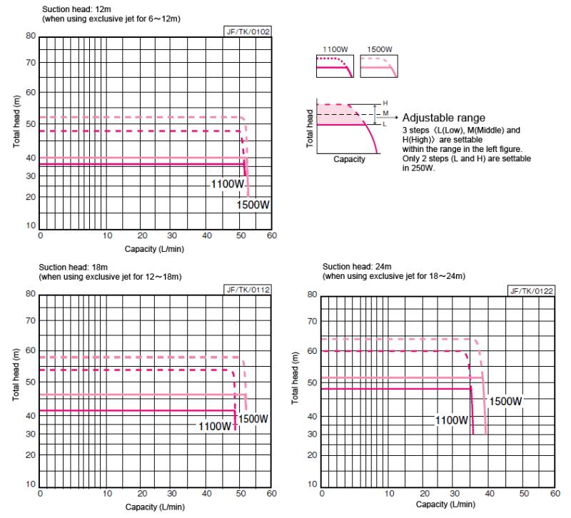
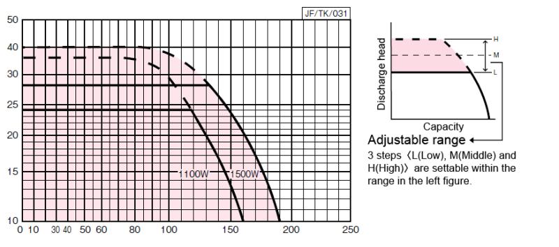
Selection chartNOTEActual performance may slightly differ from the values in table and chart. Values in table show standard characteristics.
For deep well 1100 & 1500W
Specificiation tableNOTEActual performance may slightly differ from the values in table and chart. Values in table show standard characteristics.
60Hz
深井戸用
small water amount stop rate: 10L/min, accumulator volume: 2L
| 32 | JF1100
JF1100S2 | 1100 | Three phase (Single phase 200V) | 12 | 32 | 52 | 20〈26〉[32] | 24〈30〉[36] | 30 | 30 | N20 or N30 (6~12m) | DL |
| 32 | JF1100
JF1100S2 | 1100 | Three phase (Single phase 200V) | 18 | 38 | 45 | 20〈26〉[32] | 24〈30〉[36] | 30 | 30 | N20 or N30 (12~18m) | DL |
| 32 | JF1100
JF1100S2 | 1100 | Three phase (Single phase 200V) | 24 | 44 | 35 | 20〈26〉[32] | 24〈30〉[36] | 30 | 30 | N24 or N34 (18~24m) | DL |
| 32 | JF1500 | 1500 | Three phase 200V | 12 | 36 | 52 | 24〈30〉[36] | 28〈34〉[40] | 30 | 30 | N20 or N30 (6~12m) | DL |
| 32 | JF1500 | 1500 | Three phase 200V | 18 | 42 | 50 | 24〈30〉[36] | 28〈34〉[40] | 30 | 30 | N20 or N30 (12~18m) | DL |
| 32 | JF1500 | 1500 | Three phase 200V | 24 | 48 | 35 | 24〈30〉[36] | 28〈34〉[40] | 30 | 30 | N24 or N34 (18~24m) | DL |
*Operation characteristics enclosed in < > shows the value when Fine sensor set at M, and [ ] shows the value when Fine sensor set at H. H is default.
*2 Jet set N20 & N23 have built-in Foot valve.
Also, use Jet set N30 or N33 in case the well water level drops under Jet part. (It is not capable of drainage in the pipe, because of foot valve without lever.)
深井戸用
small water amount stop rate: 10L/min, accumulator volume: 2L
| 32 | JF1100
JF1100S2 | 1100 | Three phase (Single phase 200V) | 39 | 104 | 13 | 20〈26〉[32] | 24〈30〉[36] | 30 | 30 | N20 or N30 (6~12m) | DL |
|---|
| 32 | JF1100
JF1100S2 | 1100 | Three phase (Single phase 200V) | 59 | 124 | 11 | 20〈26〉[32] | 24〈30〉[36] | 30 | 30 | N20 or N30 (12~18m) | DL |
|---|
| 32 | JF1100
JF1100S2 | 1100 | Three phase (Single phase 200V) | 78 | 144 | 9 | 20〈26〉[32] | 24〈30〉[36] | 30 | 30 | N24 or N34 (18~24m) | DL |
|---|
| 32 | JF1500 | 1500 | Three phase 200V | 39 | 118 | 13 | 24〈30〉[36] | 28〈34〉[40] | 30 | 30 | N20 or N30 (6~12m) | DL |
|---|
| 32 | JF1500 | 1500 | Three phase 200V | 59 | 137 | 13 | 24〈30〉[36] | 28〈34〉[40] | 30 | 30 | N20 or N30 (12~18m) | DL |
|---|
| 32 | JF1500 | 1500 | Three phase 200V | 78 | 157 | 9 | 24〈30〉[36] | 28〈34〉[40] | 30 | 30 | N24 or N34 (18~24m) | DL |
|---|
*Operation characteristics enclosed in < > shows the value when Fine sensor set at M, and [ ] shows the value when Fine sensor set at H. H is default.
*2 Jet set N20 & N23 have built-in Foot valve.
Also, use Jet set N30 or N33 in case the well water level drops under Jet part. (It is not capable of drainage in the pipe, because of foot valve without lever.)
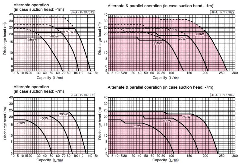
Selection chartNOTEActual performance may slightly differ from the values in table and chart. Values in table show standard characteristics.
For shallow well (in case total suction head: -7m) 250~750W
Discharge head(m)
Capacity(L/min)
Specificiation tableNOTEActual performance may slightly differ from the values in table and chart. Values in table show standard characteristics.
60Hz
For shallow well, small water amount stop rate: 4L/min
| 25 | 25 | JF250S | 250 | Single phase 100V | 21 | 28 | 14 [20] | 18 [24] | 1 | A01 | DL |
| 25 | 32 | JF400S | 400 | Single phase 100V | 24 | 43 | 17<23>[29] | 21<27>[33] | 1 | A02 | DL |
| 25 | 32 | JF400S2 | 400 | Single phase 200V | 24 | 43 | 17<23>[29] | 21<27>[33] | 1 | A02 | DL |
| 25 | 32 | JF400T | 400 | Three phase 200V | 24 | 43 | 17<23>[29] | 21<27>[33] | 1 | A02 | DL |
| 25 | 32 | JF750S2 | 750 | Single phase 200V | 27 | 65 | 20<26>[32] | 24<30>[36] | 1 | A03 | DL |
| 25 | 32 | JF750 | 750 | Three phase 200V | 27 | 65 | 20<26>[32] | 24<30>[36] | 1 | A03 | DL |
*Operation characteristics enclosed in < > shows the value when Fine sensor set at M, and [ ] shows the value when Fine sensor set at H. Default setting of 250W model is H, and 400W & 750W model are M.
When combining with reservoir, default pressure setting (M) is recommended.
For shallow well, small water amount stop rate: 4L/min
| 25 | 25 | JF250S | 250 | Single phase 100V | 68 | 7 | 14 [20] | 18 [24] | 1 | A01 | DL |
|---|
| 25 | 32 | JF400S | 400 | Single phase 100V | 78 | 11 | 17<23>[29] | 21<27>[33] | 1 | A02 | DL |
|---|
| 25 | 32 | JF400S2 | 400 | Single phase 200V | 78 | 11 | 17<23>[29] | 21<27>[33] | 1 | A02 | DL |
|---|
| 25 | 32 | JF400T | 400 | Three phase 200V | 78 | 11 | 17<23>[29] | 21<27>[33] | 1 | A02 | DL |
|---|
| 25 | 32 | JF750S2 | 750 | Single phase 200V | 88 | 17 | 20<26>[32] | 24<30>[36] | 1 | A03 | DL |
|---|
| 25 | 32 | JF750 | 750 | Three phase 200V | 88 | 17 | 20<26>[32] | 24<30>[36] | 1 | A03 | DL |
|---|
*Operation characteristics enclosed in < > shows the value when Fine sensor set at M, and [ ] shows the value when Fine sensor set at H. Default setting of 250W model is H, and 400W & 750W model are M.
When combining with reservoir, default pressure setting (M) is recommended.
Selection chartNOTEActual performance may slightly differ from the values in table and chart. Values in table show standard characteristics.
For reservoir (in case total suction head: -1m) 250~750W
Discharge head(m)
Capacity(L/min)
Specificiation tableNOTEActual performance may slightly differ from the values in table and chart. Values in table show standard characteristics.
60Hz
For reservoir, small water amount stop rate: 4L/min
| 25 | 25 | Individual | JF250S | 250 | Single phase 100V | 21 | 28 | 14 [20] | 18 [24] | 1 | A01 | DL | DL | DL | DL | DL | DL |
| 25 | 32 | Individual | JF400S | 400 | Single phase 100V | 24 | 43 | 17<23>[29] | 21<27>[33] | 1 | A02 | DL | DL | DL | DL | DL | DL |
| 25 | 32 | Individual | JF400S2 | 400 | Single phase 200V | 24 | 43 | 17<23>[29] | 21<27>[33] | 1 | A02 | DL | DL | DL | DL | DL | DL |
| 25 | 32 | Individual | JF400T | 400 | Three phase 200V | 24 | 43 | 17<23>[29] | 21<27>[33] | 1 | A02 | DL | DL | DL | DL | DL | DL |
| 25 | 32 | Individual | JF750S2 | 750 | Single phase 200V | 27 | 65 | 20<26>[32] | 24<30>[36] | 1 | A03 | DL | DL | DL | DL | DL | DL |
| 25 | 32 | Individual | JF750 | 750 | Three phase 200V | 27 | 65 | 20<26>[32] | 24<30>[36] | 1 | A03 | DL | DL | DL | DL | DL | DL |
*Operation characteristics enclosed in < > shows the value when Fine sensor set at M, and [ ] shows the value when Fine sensor set at H. Default setting of 250W model is H, and 400W & 750W model are M.
When combining with reservoir, default pressure setting (M) is recommended.
For reservoir, small water amount stop rate: 4L/min
| 25 | 25 | Individual | JF250S | 250 | Single phase 100V | 68 | 7 | 14 [20] | 18 [24] | 1 | A01 | DL | DL | DL | DL | DL | DL |
|---|
| 25 | 32 | Individual | JF400S | 400 | Single phase 100V | 78 | 11 | 17<23>[29] | 21<27>[33] | 1 | A02 | DL | DL | DL | DL | DL | DL |
|---|
| 25 | 32 | Individual | JF400S2 | 400 | Single phase 200V | 78 | 11 | 17<23>[29] | 21<27>[33] | 1 | A02 | DL | DL | DL | DL | DL | DL |
|---|
| 25 | 32 | Individual | JF400T | 400 | Three phase 200V | 78 | 11 | 17<23>[29] | 21<27>[33] | 1 | A02 | DL | DL | DL | DL | DL | DL |
|---|
| 25 | 32 | Individual | JF750S2 | 750 | Single phase 200V | 88 | 17 | 20<26>[32] | 24<30>[36] | 1 | A03 | DL | DL | DL | DL | DL | DL |
|---|
| 25 | 32 | Individual | JF750 | 750 | Three phase 200V | 88 | 17 | 20<26>[32] | 24<30>[36] | 1 | A03 | DL | DL | DL | DL | DL | DL |
|---|
*Operation characteristics enclosed in < > shows the value when Fine sensor set at M, and [ ] shows the value when Fine sensor set at H. Default setting of 250W model is H, and 400W & 750W model are M.
When combining with reservoir, default pressure setting (M) is recommended.
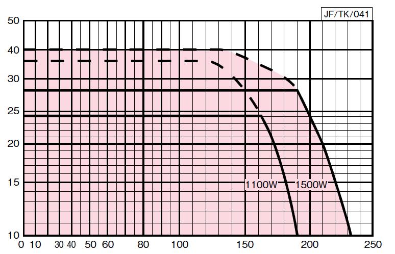
Selection chartNOTEActual performance may slightly differ from the values in table and chart. Values in table show standard characteristics.
For shallow well (in case total suction head: -6m [actual suction head: within -4m]) 1100 & 1500W
Discharge head(m)
Capacity(L/min)
Specificiation tableNOTEActual performance may slightly differ from the values in table and chart. Values in table show standard characteristics.
60Hz
For shallow well, small water amount stop rate: 10L/min
| 32 | 40 | JF1100 | 1100 | Three phase 200V | 27 | 120 | 20 26[32] | 24<30>[36] | 2 | A04 | DL |
| 32 | 40 | JF1100S2 | 1100 | Single phase 200V | 27 | 120 | 20 26[32] | 24<30>[36] | 2 | A04 | DL |
| 32 | 40 | JF1500 | 1500 | Three phase 200V | 31 | 140 | 24<30>[36] | 28<34>[40] | 2 | A04 | DL |
*Operation characteristics enclosed in < > shows the value when Fine sensor set at M, and [ ] shows the value when Fine sensor set at H. H is default.
For shallow well, small water amount stop rate: 10L/min
| 32 | 40 | JF1100 | 1100 | Three phase 200V | 88 | 31 | 20 26[32] | 24<30>[36] | 2 | A04 | DL |
|---|
| 32 | 40 | JF1100S2 | 1100 | Single phase 200V | 88 | 31 | 20 26[32] | 24<30>[36] | 2 | A04 | DL |
|---|
| 32 | 40 | JF1500 | 1500 | Three phase 200V | 101 | 36 | 24<30>[36] | 28<34>[40] | 2 | A04 | DL |
|---|
*Operation characteristics enclosed in < > shows the value when Fine sensor set at M, and [ ] shows the value when Fine sensor set at H. H is default.
Selection chartNOTEActual performance may slightly differ from the values in table and chart. Values in table show standard characteristics.
For reservoir (in case total suction head: -3m [actual suction head: within -1m]) 1100 & 1500W
Discharge head(m)
Capacity(L/min)
Specificiation tableNOTEActual performance may slightly differ from the values in table and chart. Values in table show standard characteristics.
60Hz
For reservoir, small water amount stop rate: 10L/min
| 32 | 40 | JF1100 | 1100 | Three phase 200V | 27 | 160 | 20 26[32] | 24<30>[36] | 2 | A05 |
| 32 | 40 | JF1100S2 | 1100 | Single phase 200V | 27 | 160 | 20 26[32] | 24<30>[36] | 2 | A05 |
| 32 | 40 | JF1500 | 1500 | Three phase 200V | 31 | 180 | 24<30>[36] | 28<34>[40] | 2 | A05 |
*Operation characteristics enclosed in < > shows the value when Fine sensor set at M, and [ ] shows the value when Fine sensor set at H.
When combining with reservoir, default pressure setting (M) is recommended.
For reservoir, small water amount stop rate: 10L/min
| 32 | 40 | JF1100 | 1100 | Three phase 200V | 88 | 42 | 20 26[32] | 24<30>[36] | 2 | A05 |
|---|
| 32 | 40 | JF1100S2 | 1100 | Single phase 200V | 88 | 42 | 20 26[32] | 24<30>[36] | 2 | A05 |
|---|
| 32 | 40 | JF1500 | 1500 | Three phase 200V | 101 | 47 | 24<30>[36] | 28<34>[40] | 2 | A05 |
|---|
*Operation characteristics enclosed in < > shows the value when Fine sensor set at M, and [ ] shows the value when Fine sensor set at H.
When combining with reservoir, default pressure setting (M) is recommended.